

How to Identify and Eliminate Conducted EMI in DC Power Lines: A Practical Engineering Guide

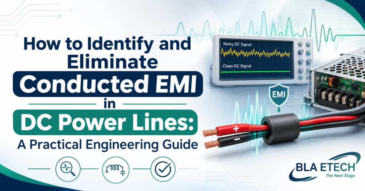
Conducted EMI is unwanted high-frequency noise that travels along a power or signal cable instead of radiating through the air. On a DC power line, it usually comes from switching converters, motor drives, relays and digital loads, and it can disturb other equipment on the same supply or cause a product to fail compliance testing. This guide covers how to confirm the noise, work out its type and source, and choose a fix. It also explains what to ask an EMI filter manufacturer once you know what the line needs.
Recognise the Symptoms First
Conducted noise rarely announces itself. Typical signs include a product that fails a conducted emissions test by a few decibels, sensors that give unstable readings when a motor starts, communication errors that appear only when certain loads switch, and audible hum or buzz in audio circuits. If problems change with load or switching frequency, noise on the supply is a likely suspect.
Measure Before You Guess
Use the right tools
For a proper look, use a spectrum analyser with a line impedance stabilisation network (LISN) or its DC equivalent, which presents a defined impedance and provides a measurement port. For early debugging, an oscilloscope with a short ground spring and bandwidth limit can show ripple and spikes at the converter output. A near-field probe set helps locate hot spots on the board.
Separate the two noise types
Differential mode noise appears between the positive and return conductors. Common mode noise appears equally on both conductors relative to ground or chassis. Many designs have both. A current probe clamped around both conductors together reads common mode current, and a probe around one conductor reads the combined current. Knowing which dominates decides what component helps most.
Find the Source
Switch circuits off one at a time and watch the spectrum. Check the switching frequency and its harmonics, since noise spikes often line up with them. Fast edges on MOSFETs and diodes, parasitic capacitance to a heatsink, and long loops in the power path are common contributors. Cables act as antennas and carry common mode current if there is a path to ground through a heatsink, chassis or shield.
Reduce the Noise at the Source
A filter works better when the source is quieter.
Slow the switching edges slightly, using gate resistors or snubbers, accepting a small efficiency trade-off. Shrink the high-current loop area in layout. Place input capacitors close to the switch. Tie heatsinks to a stable potential or isolate them with a small capacitance to limit common mode coupling. Use twisted or tightly coupled conductors for supply and return.
Choose and Size a DC EMI Power Line Filter
A DC EMI power line filter typically combines a common mode choke, X capacitors across the line and Y capacitors to ground, sometimes with differential mode inductance.
Match the filter to the noise
If common mode noise dominates, prioritise a choke with high impedance across the problem band. If differential mode noise dominates, increase X capacitance and differential inductance. A choke with leakage inductance can help both modes, but check saturation.
Check ratings that matter in DC
Confirm the voltage rating includes transients. Check the continuous current rating at your real ambient temperature, since heat reduces capacity. In DC, the choke carries the full load current in each direction, so saturation margin matters. Consider inrush current and startup behaviour if large capacitors are involved.
Remember what datasheets assume
Insertion loss curves are normally measured in a 50-ohm system, while real DC sources and loads often have very different impedance. Treat datasheet figures as a guide and confirm on your own setup. Interaction between a filter and a switching converter can also cause instability, so check for oscillation or peaking at the converter input.
Install the Filter Properly
Place it at the point where the cable enters the equipment, with short, wide connections. Keep input and output wiring apart so noise does not couple past the filter. Make the ground or chassis connection short and low inductance, ideally to a clean metal surface. Avoid routing noisy cables across the filter body.
Verify and Iterate
Re-measure with the same method used earlier, and compare spectra before and after. If margin is thin, small layout changes can add useful decibels. Record the setup, because small changes in cable length or grounding can shift results on a later test day. Aim for a few decibels of margin to cover production variation.
When to Involve a Specialist
If you have tried standard parts and results are marginal, discuss the application with an EMI filter manufacturer that can review your measurements, current, ambient temperature and mounting constraints. A custom or modified design is sometimes more efficient than stacking several standard filters.
BLA Etech supplies EMI filters and works with engineers on application questions, so sharing your spectrum plots and operating conditions helps them recommend a suitable part.
Conclusion
To eliminate conducted EMI in DC lines, measure first, separate common mode from differential mode, reduce noise at the source and then choose a filter that matches the noise and the electrical ratings. Install it at the cable entry with clean grounding and verify with a repeat measurement. If you need a second opinion on a stubborn problem, BLA Etech can review your data and suggest the next step.












Comments (0)