

How Can the Bourns Potentiometer Support Digital Control?
Discover how the Bourns Potentiometer supports digital controls, with practical guidance on adjustment limits, signal filtering, calibration and start-up.


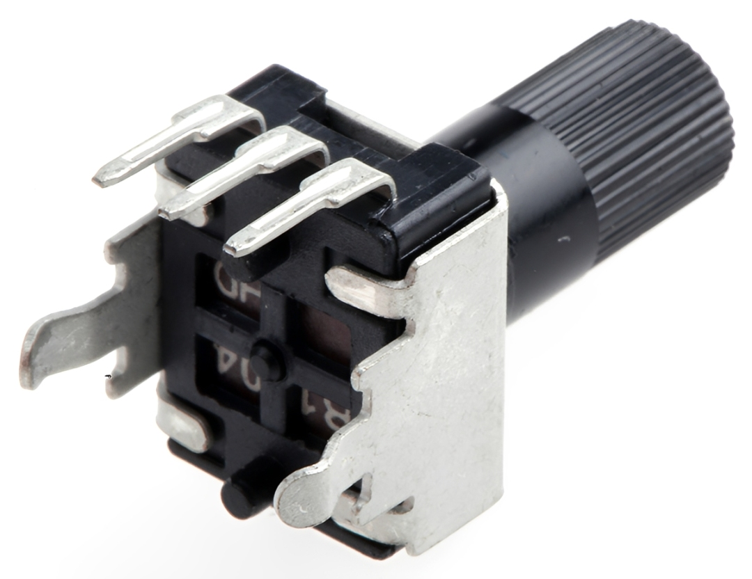
A rotary dial can make electronic equipment easier to adjust, even when software manages everything behind the panel. The Bourns Potentiometer PTV09A-4020U-B104 offers a manual input that designers can connect to suitable signal-conditioning and conversion circuitry for this purpose.
This model provides 100 kΩ nominal resistance, a linear taper and a carbon element, with a rated power of 0.05 W. It is a mechanical analogue component; digital interpretation comes from the surrounding electronics.
That combination opens useful design possibilities. A familiar dial can set a timer interval, adjust a lighting command or select a reference value while firmware determines how the equipment responds.
What Should Each Dial Position Mean?
Begin with the intended user action. Decide whether the dial should make fine adjustments, cover a broad range or select several distinct operating levels.
Suitable Microcontrollers with an analogue-to-digital converter can read a compatible input voltage and translate it into a software setting. The designer then defines the relationship between the measured input and the commanded output.
For example, an illustrative timer interface could map the usable dial travel to a range of 5–60 seconds. This would be a programmed application behaviour, rather than a built-in function of the potentiometer.
Write down the minimum, maximum and preferred direction of adjustment before developing the interface.
How Can the Adjustment Range Be Limited?
Some applications need the dial to operate within a restricted electrical range. A designer can add fixed resistors at the ends of a potentiometer divider to keep its normal output away from the supply rails.
Through Hole Resistors can support this arrangement during suitable prototype or production work. Their values must be calculated alongside the potentiometer resistance, supply voltage and input loading.
Allow for component tolerances when predicting the limits. The PTV09 series specifies a standard resistance tolerance of ±20%, so calculations based only on exactly 100 kΩ will not describe every unit.
Also distinguish a normal adjustment limit from fault protection. Additional circuitry or software checks may be needed to handle an open connection.
Why Does the Converter Need Time to Read the Signal?
An analogue-to-digital converter, usually shortened to ADC, needs an appropriate input signal and enough time to acquire it.
Many ADCs charge an internal sampling capacitor before conversion. Microchip explains that the source impedance influences the time required for that capacitor to settle.
This matters with a 100 kΩ potentiometer. In an ideal divider driven by low-impedance supplies, its midpoint presents approximately 25 kΩ source resistance, calculated from two 50 kΩ sections in parallel.
Check the selected ADC’s requirements across the whole dial range. Depending on the circuit, a longer acquisition interval or suitable buffer may be necessary. A matching voltage range alone does not establish compatibility.
How Can Small Reading Fluctuations Be Controlled?
A stationary dial should not leave a displayed setting continually jumping between neighbouring values. First identify whether the variation comes from electrical noise, the conversion arrangement or movement at the contact.
A designed resistor-capacitor filter can attenuate higher-frequency interference before conversion. Suitable Ceramic Capacitors may form part of that filter, with capacitance, voltage rating and dielectric selected for the circuit.
However, filtering introduces settling time. Increasing capacitance without reviewing the complete input network can make adjustment feel slow.
Firmware can also average readings or apply a small update threshold. Treat these as design options to evaluate: the operator should see a steady setting while deliberate changes remain easy to make.
What Does Calibration Add to the Interface?
Calibration establishes how measured input values correspond to the intended control range. It can be useful when the product needs consistent endpoint behaviour across assembled units.
During development, determine the readings reached at the two usable ends of travel. Software can then map that interval to the required output range.
Consider these questions:
-
Can the user reach both specified settings?
-
Does useful adjustment extend across most of the rotation?
-
Are intermediate values comfortable to select?
-
What happens if a reading falls outside the calibrated interval?
Endpoint calibration does not remove every source of error. Track behaviour, conversion accuracy and environmental changes still require consideration.
When Is Stored Calibration Useful?
Equipment that performs calibration during manufacture may need to retain those values after power is removed.
Compatible EEPROM can store calibration data where the controller’s internal memory does not meet the requirement. Check the interface, supply voltage, retention specification and write endurance of the selected memory.
EEPROM endurance is finite, so avoid saving every individual ADC reading. A practical design might save calibration only after an approved adjustment routine completes.
Include a way to recognise missing or invalid calibration data. The product should have a defined response, such as requesting setup or using an approved default configuration.
What Should Happen When Power Returns?
Start-up behaviour deserves its own design decision. Should the equipment immediately follow the physical dial position, restore a stored setting or wait for user confirmation?
A saved setting can differ from the current dial position if someone moved the control while power was off.
Define how the interface resolves that difference. For example, software might wait until the dial reaches the stored value before allowing it to take over.
Test the chosen behaviour with representative users, particularly when the controlled output could change abruptly.
How Can the Finished Response Be Evaluated?
Suitable Oscilloscopes can help observe the analogue signal during rotation and compare it with the controller’s reported values. Use appropriate probes and account for their loading.
Include slow movements, rapid changes, pauses and power cycles in the evaluation. Record both signal behaviour and the time taken for the commanded output to respond.
Keep the approved circuit values, firmware settings and calibration method together in the design record. Specify the full PTV09A-4020U-B104 part number so future builds preserve the intended Bourns Potentiometer configuration.












Comments (0)