

What Should Engineers Know Before Choosing Varactor Diodes?
Varactor diodes are semiconductor devices designed to provide voltage-controlled capacitance for RF tuning, oscillators, filters, frequency synthesis, and communication circuits. This guide explains how varactor diodes work, their key specifications, applications, advantages, and important selection considerations.

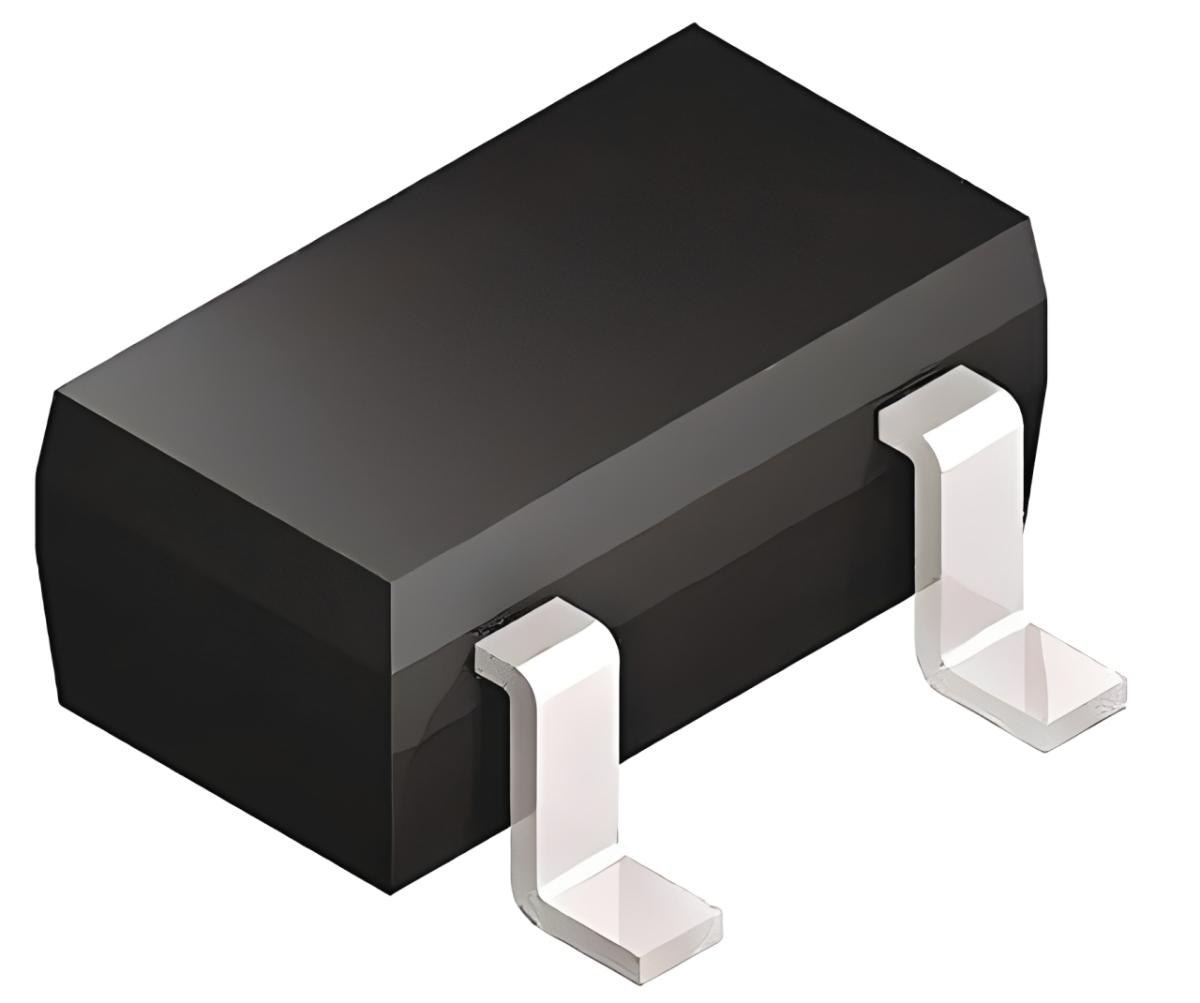
Varactor diodes are widely used in electronic systems that require adjustable capacitance, accurate frequency control, and compact circuit design. Unlike standard diodes, these components are specifically intended to operate under reverse-bias conditions, where their junction capacitance changes according to the applied voltage.
This makes varactor diodes especially useful in RF circuits, tunable filters, oscillators, communication systems, and other frequency-sensitive applications. However, selecting the right device requires more than simply checking its capacitance value. Engineers must consider tuning range, quality factor, reverse voltage, temperature behaviour, package style, and the way the diode interacts with the rest of the circuit.
Understanding these factors can help improve tuning accuracy, efficiency, and long-term reliability.
Why Is the Capacitance-Voltage Relationship Important?
The defining characteristic of a varactor diode is its ability to change capacitance as the reverse-bias voltage changes.
Inside the diode, the PN junction forms a depletion region. This area contains very few mobile charge carriers and behaves as an insulating layer between the semiconductor regions.
As reverse voltage increases, the depletion region becomes wider. The effective distance between the conductive regions therefore increases, causing the junction capacitance to decrease.
When reverse voltage is reduced, the depletion region becomes narrower and the capacitance increases.
This relationship gives designers a practical method of controlling capacitance through voltage rather than physical movement.
What Is a Tuning Range in Varactor Applications?
The tuning range describes how far a circuit can shift its operating frequency as the diode capacitance changes.
This depends partly on the minimum and maximum capacitance values available from the varactor diode, but it also depends on the surrounding components.
A broad capacitance range can be beneficial in applications that require significant frequency movement, such as:
- Multi-channel radio systems
- Tunable RF front ends
- Frequency-agile communication devices
- Signal generators
- Wide-range oscillators
- Adaptive filters
A narrower tuning range may be preferable in applications where stability and fine adjustment are more important than large frequency changes.
How Does the Capacitance Ratio Affect Performance?
The capacitance ratio compares the capacitance available at different reverse-bias voltages.
A larger ratio generally gives the circuit more tuning flexibility. However, a high ratio does not automatically make a diode suitable for every design.
Engineers should consider how smoothly the capacitance changes across the required voltage range. A circuit that needs precise frequency adjustment may benefit from a predictable capacitance curve rather than simply the largest possible ratio.
For this reason, manufacturer graphs can be just as important as headline datasheet values.
Why Is Q Factor Important in RF Design?
The quality factor, or Q factor, describes the relationship between useful reactive behaviour and electrical losses.
In RF circuits, a high Q factor is often desirable because excessive internal resistance can reduce efficiency and weaken resonance.
This becomes particularly important in:
- Resonant networks
- Tunable filters
- RF oscillators
- High-frequency receivers
- Frequency multipliers
- Narrow-band communication circuits
When comparing varactor diodes, engineers should check the frequency at which the Q factor is specified because the value can vary considerably with operating conditions.
What Does Series Resistance Change in a Circuit?
A real varactor diode is not a perfect capacitor. It includes small resistive and parasitic elements that can influence performance.
Series resistance can introduce power loss and lower the effective Q factor of the tuning network.
At relatively low frequencies, these effects may be minor. At higher RF frequencies, however, even small internal losses can become significant.
Designers working with demanding RF systems should therefore evaluate both the nominal capacitance and the diode's loss characteristics.
How Much Reverse Voltage Does a Varactor Diode Need?
Varactor diodes require reverse bias to operate correctly.
The control voltage determines the junction capacitance, but the applied voltage must remain within the manufacturer's specified limits.
A suitable design should consider:
- Minimum useful tuning voltage
- Maximum reverse-voltage rating
- Available circuit-control voltage
- Required capacitance range
- Voltage stability
- Protection against unintended forward bias
Applying excessive reverse voltage can damage the device, while insufficient bias may prevent the required tuning range from being achieved.
Why Is Bias Circuit Design So Important?
The varactor diode does not operate independently. It must be connected to a bias network that provides the required control voltage without disturbing the RF signal.
A poorly designed bias circuit can introduce noise, unwanted signal paths, or instability.
Typical design goals include:
- Keeping RF energy away from the control line
- Preventing unwanted loading of the resonant circuit
- Maintaining stable DC bias
- Reducing noise from the control source
- Protecting the diode from voltage transients
Engineers may use resistors, RF chokes, bypass capacitors, or other isolation techniques depending on the frequency and circuit architecture.
How Are Varactor Diodes Used in Automatic Frequency Control?
Automatic frequency control systems continuously correct unwanted frequency changes.
A control circuit can detect a frequency error and adjust the voltage applied to a varactor diode. The resulting capacitance change modifies the resonant frequency until the circuit returns to the required operating point.
This technique can help compensate for factors such as:
- Component tolerances
- Temperature changes
- Supply variations
- Ageing effects
- Small oscillator drift
Electronic correction allows the system to maintain more consistent performance without manual adjustment.
What Is the Role of Varactor Diodes in Tunable Resonators?
Resonant circuits are designed to respond strongly at particular frequencies.
A fixed resonator uses components with predetermined values, but a tunable resonator requires at least one adjustable element.
A varactor diode can provide this adjustable capacitance electronically.
By changing the bias voltage, the resonant frequency can be moved across a controlled range. This makes varactors useful in systems that must adapt dynamically during operation.
Applications may include wireless transceivers, communication test systems, RF sensing equipment, and frequency-selective electronics.
Why Does the Package Style Matter?
The physical package of a varactor diode can influence circuit performance, especially at high frequencies.
Lead length, pad geometry, and internal package construction introduce parasitic capacitance and inductance.
Common design considerations include:
- Available PCB space
- Surface-mount assembly requirements
- Operating frequency
- Thermal performance
- Parasitic effects
- Automated manufacturing compatibility
A small surface-mount package may be ideal for compact RF equipment, but designers must still review its electrical characteristics carefully.
How Does PCB Layout Influence Tuning Accuracy?
At RF frequencies, PCB tracks and component placement become part of the circuit.
A long trace can introduce unwanted inductance, while nearby copper areas may create additional capacitance. These effects can shift the expected tuning range.
Good layout practices may include:
- Keeping critical RF paths short
- Placing the varactor close to associated inductors
- Using consistent grounding
- Avoiding unnecessary copper near sensitive nodes
- Separating noisy digital lines from analogue tuning sections
- Minimising uncontrolled parasitic capacitance
Careful layout helps ensure that the measured circuit behaves more closely to the original design calculations.
Where Are Varactor Diodes Most Valuable?
Varactor diodes are especially useful where circuits need precise electronic control of frequency or resonance.
Typical uses include:
- RF tuners
- Voltage-controlled oscillators
- Phase-locked loops
- Frequency synthesizers
- Tunable filters
- Signal generators
- Communication receivers
- Wireless transmitters
- Microwave circuits
- Automatic frequency-control systems
Their usefulness comes from combining small size with fast electronic adjustment.
Why Is Proper Varactor Diode Selection So Important?
Choosing a varactor diode is not simply a matter of selecting the largest capacitance range. The component must suit the actual frequency, bias voltage, tuning requirement, loss target, package constraints, and environmental conditions of the application.
A carefully selected diode can help provide smooth frequency adjustment, efficient RF performance, and dependable long-term operation.
Varactor diodes remain important because they offer a practical bridge between analogue RF behaviour and electronic control. By converting changes in voltage into controlled changes in capacitance, they allow modern circuits to tune, adapt, and respond without mechanical adjustment.
For engineers designing compact and frequency-sensitive systems, understanding the electrical characteristics of varactor diodes is essential to achieving stable, accurate, and efficient performance.














Comments (0)