

How to Calibrate and Maintain Your Thermal Conductivity Gas Analyzer
Learn how to calibrate and maintain a Thermal Conductivity Analyzer for accurate gas measurements, prevent sensor drift, and ensure reliable process monitoring.
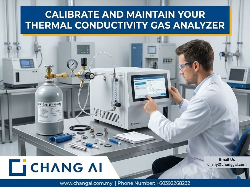
To calibrate a thermal conductivity gas analyzer, you expose the sensor to a known zero gas and a certified span gas, record the baseline responses, then adjust the analyzer output to match the expected values. Routine maintenance includes cleaning the sensor cell, checking for flow restrictions, and verifying electronics stability. Together, these steps prevent sensor drift and extend calibration intervals.
A well-maintained thermal conductivity analyzer is the difference between reliable process control and costly measurement errors. Whether you're monitoring hydrogen purity in a refinery or measuring CO₂ in a fermentation loop, calibration drift silently corrupts your data — and by the time it's noticed, the damage is already done. This guide gives plant maintenance teams and calibration technicians a practical, step-by-step framework to keep TCD-based analyzers performing accurately, cycle after cycle.
Why Thermal Conductivity Analyzers Drift Over Time
Thermal conductivity detectors work by measuring the heat dissipated from a heated filament or thermistor into the surrounding gas. The detector compares this to a reference cell filled with carrier gas. When process conditions change — or when contaminants coat the sensing element — the output signal shifts. This is thermal conductivity sensor drift, and it's the root cause of most calibration failures.
Common drift triggers include:
-
Particulate buildup on the detector cell walls
-
Moisture ingress into the sample line
-
Pressure fluctuations upstream of the analyzer
-
Aging of the filament or thermistor element
-
Background gas composition changes in multicomponent streams
Understanding the root cause matters. Treating drift as a calibration problem when it's actually a contamination problem just restores accuracy temporarily. You need to fix both.
Step-by-Step Calibration Procedure for a TCD Analyzer
Before starting, confirm that the analyzer has been running for at least 30 minutes to reach thermal equilibrium. Cold calibrations produce inconsistent results. Have your certified calibration gases ready — zero gas and span gas — with documentation of their certified concentrations.
Step 1: Zero Calibration
Introduce the zero gas (typically pure nitrogen or the matrix gas without the target component) into the sample inlet at the specified flow rate. Allow the reading to stabilize — this usually takes 2 to 5 minutes depending on cell volume. Once stable, adjust the zero setpoint in the analyzer to read 0.0% or 0 ppm as per your range.
Step 2: Span Calibration
Switch to the span gas — a certified mixture at 80–90% of full-scale range. Wait for stabilization again. Adjust the span setpoint until the displayed value matches the certified concentration on the gas cylinder certificate. Record the pre-adjustment and post-adjustment readings in your calibration log.
Step 3: Linearity Verification
For critical applications, introduce a mid-range gas (typically 40–50% of full scale) without adjusting anything. If the displayed value falls within ±2% of the certified value, your analyzer is linear across the range. If it doesn't, this indicates a non-linearity issue in the detector — not a simple calibration problem.
Step 4: Return to Process and Document
Switch back to the live sample stream. Record time, ambient conditions, gas certificate numbers, pre/post values, and the technician's name. Proper TCD sensor calibration documentation is not just good practice — it's often a regulatory requirement under ISO 17025-aligned quality systems.
Gas Analyzer Maintenance: What to Do Between Calibrations
Calibration intervals only stay long when the hardware between calibrations is properly cared for. Here's what a structured gas analyzer maintenance routine looks like in practice.
Monthly Checks
-
Inspect sample conditioning filters and replace if discoloured or pressure drop has increased
-
Check flow rates at the sample inlet and verify against manufacturer specifications
-
Inspect tubing fittings for any sign of moisture, corrosion, or leaks
-
Verify that the reference cell (if applicable) is sealed and uncontaminated
Quarterly Checks
-
Perform a zero and span check using certified gases — record without adjusting to see natural drift magnitude
-
Clean the detector cell if accessible, using dry nitrogen purge per manufacturer guidelines
-
Inspect the sample pump (if equipped) for wear and flow consistency
-
Check alarm setpoints and verify they still match current process requirements
Annual Maintenance
-
Full calibration with linearity check across the measurement range
-
Filament or thermistor resistance check to detect aging before failure
-
Electronics board inspection for corrosion, loose connections, and temperature stability
-
Replace critical consumables: filters, desiccants, flow controllers as applicable
How to Extend Your Calibration Interval Without Losing Accuracy
Most manufacturers recommend calibration every 3 to 6 months. With the right practices, many plant teams extend this to 12 months while maintaining measurement integrity. Here's how.
|
Practice |
Impact on Calibration Interval
|
|---|---|
|
Use a coalescing pre-filter on the sample line |
Prevents moisture and particulate from reaching the cell |
|
Maintain stable sample flow rate |
Reduces pressure-induced zero shift |
|
Keep analyzer enclosure within rated temperature range |
Minimises thermal baseline drift |
|
Log drift trend data over time |
Allows predictive calibration before accuracy is compromised |
|
Use certified reference gases within shelf-life period |
Ensures span calibration is based on traceable values |
Trend logging is the most underused tool in calibration management. When you record drift magnitude at every check — even when you don't adjust — you build a drift rate profile. If your analyzer typically drifts 0.3% per month, you know with confidence that a 12-month interval keeps you within a ±4% total drift budget.
Recognising When Calibration Won't Fix the Problem
There are situations where repeated calibration is masking a hardware fault. Watch for these warning signs:
-
Erratic zero baseline: If the zero reading jumps even with stable reference gas, the detector cell may be contaminated or the electronics may have a grounding issue.
-
Span response that degrades within days: This often indicates filament degradation or a reference cell leak — not a gas supply problem.
-
Large difference between pre-clean and post-clean calibration: If cleaning the sample path dramatically changes the span reading, contamination was affecting measurement — not drift.
-
Non-repeatability across identical calibrations: Suggests a flow control problem or intermittent electrical fault.
In these cases, recalibration restores short-term accuracy but doesn't address the underlying failure. Log these events, escalate for component inspection, and avoid extending calibration intervals until the root cause is resolved.
Calibration Gas Selection and Traceability
The quality of your calibration result is only as good as the gas you calibrate with. In Malaysia, calibration gas suppliers certified under SAMM (Skim Akreditasi Makmal Malaysia) provide traceable gas mixtures that align with national metrology standards. Always request a certificate of analysis with each cylinder, and log the cylinder serial number against each calibration record.
For binary gas analyzers — such as those measuring hydrogen in nitrogen — your span gas composition should closely match the expected process background. Using the wrong balance gas introduces a cross-sensitivity error that no amount of span adjustment will fully correct.
Keeping Your Thermal Conductivity Analyzer Field-Ready
The teams that get the longest life from their analyzers share one habit: they treat the analyzer as a precision instrument, not just another field device. That means clean sample conditioning, traceable calibration gases, structured maintenance logs, and drift trend tracking — not just reactive adjustments when an alarm fires.
If you're specifying or upgrading analyzer systems, the team at Changai supports plant teams across Malaysia with application engineering, calibration support, and reliable thermal conductivity analyzer solutions suited to industrial process environments.
Frequently Asked Questions
How often should a thermal conductivity analyzer be calibrated?
Most manufacturers recommend calibration every 3 to 6 months. With proper sample conditioning and drift trend monitoring, many industrial sites in Malaysia extend intervals to 12 months while remaining within acceptable accuracy limits.
What gases are used to calibrate a TCD analyzer?
Calibration requires a zero gas — typically pure nitrogen or the matrix gas without the target component — and a certified span gas at 80–90% of the analyzer's full-scale range, both with traceable certificates of analysis.
What causes thermal conductivity sensor drift?
Sensor drift is most commonly caused by particulate or moisture contamination in the detector cell, filament aging, pressure fluctuations in the sample line, or changes in background gas composition affecting the reference cell baseline.
Can I clean a TCD detector cell myself?
In many analyzers, the detector cell can be purged with dry nitrogen per the manufacturer's procedure. Physical cleaning of internal components should only be performed by qualified technicians following the OEM service manual to avoid damaging the sensing element.
What is zero/span stability and why does it matter?
Zero stability refers to how consistently the analyzer reads zero with no target gas present; span stability refers to accuracy at a known concentration. Poor stability means your process measurements are unreliable between calibration events, directly impacting product quality or safety.
How do I know if my analyzer needs maintenance rather than recalibration?
If the analyzer drifts back to its previous error within days of calibration, or shows erratic readings with stable reference gas, the issue is likely hardware — contamination, aging components, or a flow fault — rather than a calibration offset requiring adjustment.
Questions

Chang Ai Technology specializes in precision gas analysis instruments and system integration solutions for industries such as air separation, environmental protection, new energy, petrochemicals, metallurgy, and semiconductors.



Comments (0)