What Is a 4 Pin Relay Socket and How Do You Wire It?
Introduction
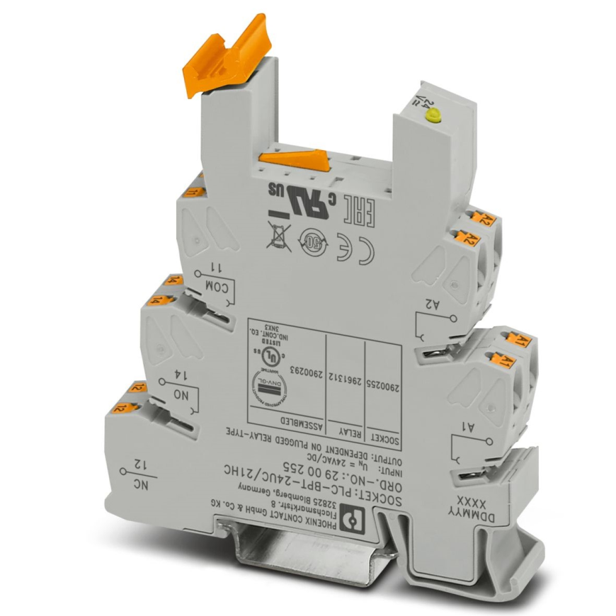
A 4 Pin Relay Socket is a compact, standardized base that securely holds a single pole relay and presents four easy-to-wire terminals. By separating the relay from direct solder joints, it speeds installation, supports quick replacement, and improves safety in electronics projects. Because the socket manages coil and contact connections, it helps prevent loose grips on cables and reduces heat at terminals during continuous loads.
Why choose a 4 Pin Relay Socket for control circuits
The 4-pin format supports a simple relay with one coil and one set of contacts. This makes it ideal for straightforward on off control in low to medium power applications. It also delivers consistent wiring for sensors, microcontrollers, and small controllers that switch higher loads such as LEDs, fans, or pumps through the relay contact.
-
Compact footprint suits crowded panels and laptops test benches.
-
Clear terminal layout reduces wiring errors and rework.
-
Replaceable design minimizes downtime during maintenance.
-
Firm retention improves vibration resistance and safety.
Understanding the pinout and terminal roles
Although layouts vary slightly by manufacturer, the common assignments are easy to remember:
-
Coil terminals: Two pins connect to the relay coil. These receive the control voltage from a driver, microprocessors, microcontrollers, or a dedicated relay module.
-
Contact terminals: Two pins form a simple switch path. In many 4-pin relays this is a normally open contact that closes when the coil is energized.
Typical labels you may encounter
-
A1 and A2 for the coil.
-
30 and 87 for the common and normally open contact in automotive patterns.
-
COM and NO in general electronics.
Always confirm the datasheet so the coil voltage, contact type, and pin numbering match your socket.
Selecting coil voltage and contact ratings
Proper selection protects components, fuses, and switches upstream. Start with the control side, then verify the load side.
-
Coil voltage: Choose a socket relay pair that matches your control rail, such as 5 V for microcontrollers, 12 V for vehicles, or 24 V for industrial controllers and contactors.
-
Coil current: Ensure the driver can supply the coil current. Add a flyback diode across the coil if not already integrated to protect sensors and logic outputs.
-
Contact rating: Size the contact for the actual load current and inrush. Inductive loads like motors, solenoids, and contactors require higher ratings than resistive loads like LEDs with drivers.
-
Insulation class and thermal limits: Check the socket material, creepage, and clearance to manage thermal rise, especially near thermal pads, oils, or dust.
Wiring a 4 Pin Relay Socket step by step
Plan the wiring path before inserting the relay. Good practices keep the panel neat and serviceable.
-
Strip cables to the recommended length and use ferrules for stranded wire.
-
Tighten terminal screws to the specified torque without over tightening.
-
Route control lines away from noisy conductors and switch-mode supplies.
-
Add a fuse or breaker on the load side for safety and compliance.
-
Label each conductor to match your schematic for quick diagnostics.
Basic control example
-
Connect the coil pins to a 12 V supply and a transistor driver from a sensor output.
-
Place a diode across A1 and A2 observing polarity.
-
Wire supply to COM and the load to NO, then return the load to ground or neutral.
-
When the sensor triggers, the coil energizes and the contact closes to power the load.
Where the 4 Pin Relay Socket fits best
You will see these sockets across many practical builds where robust switching is required and space is limited.
-
Automotive and transport harnesses with quick service needs.
-
Small panels that integrate controllers, contactors, and safety relays.
-
Test jigs for laptops, chargers, LEDs, and capacitor banks.
-
Appliance control boards using microcontrollers with external drivers.
Key specifications to check before purchase
Reading the datasheet prevents costly rework and ensures compatibility with your tools and wiring accessories.
-
Terminal type: Screw clamp, spring clamp, or solder lug connectors.
-
Wire size range: Confirm the acceptable gauge for your cables.
-
Housing material: Flame rating, temperature range, and oils resistance.
-
Mounting style: DIN rail clip, panel mount ears, or PCB stakes.
-
Relay form: Matching footprint for the chosen 4-pin relay package.
-
Environmental ratings: Humidity, shock, vibration, and ingress.
Reliability and thermal considerations
Even simple relay sockets benefit from thoughtful thermal management. Contacts dissipate heat under sustained current, and coils warm during long on cycles.
-
Maintain airflow around the socket and avoid bundling high current conductors too tightly.
-
Use thermal pads or standoffs when sockets sit near heat sources.
-
Specify relays with suitable coil resistance and consider a driver that reduces coil power after pull in.
-
Inspect grips and terminals periodically to prevent hot spots from loosened screws.
Integrating with sensors and low voltage logic
A relay isolates the low voltage domain from higher voltages used by actuators. However, the transition from logic to coil requires a driver stage.
-
Use a transistor or MOSFET with a base gate resistor and a flyback diode.
-
Add an optocoupler when sensors share long cables or harsh grounds.
-
Provide a local capacitor near the driver to handle transient current spikes.
-
Keep return paths short and direct to reduce noise on microprocessors.
Practical tips for clean, maintainable builds
These simple habits raise the quality of your assemblies and make future upgrades easier.
-
Color code cables for coil, supply, and load paths.
-
Apply clear labels to the socket and nearby switches or fuses.
-
Group sockets with compatible relays to simplify spares planning.
-
Keep a small kit of crimp ferrules, cutters, and screwdrivers as essential tools.
Common mistakes and how to avoid them
Small oversights often lead to intermittent faults or premature failure. A brief checklist helps during commissioning.
-
Misidentified pins: Cross checking the pinout prevents a short across the coil or contacts.
-
Underrated contacts: Sizing for steady current alone ignores inrush from motors or LEDs with capacitive input.
-
Missing suppression: Omitted diodes or snubbers can reset controllers or damage sensor inputs.
-
Loose terminations: Regularly recheck torque, especially after the first thermal cycles.
Final thoughts: keeping control simple and dependable
A 4 Pin Relay Socket delivers fast installation, consistent wiring, and safe isolation between logic and load. By matching coil voltage, confirming contact ratings, and applying clean wiring practices, you gain a dependable switching block for projects that span sensors, controllers, and power devices. With the right attention to thermal limits, cable routing, and surge control, the socket and relay pair will operate reliably across diverse environments, from compact electronics enclosures to small industrial panels.